Jeep Cherokee (XJ): Liftgate support rod cylinder. Liftgate support rod ball stud. Liftgate outside handle
REMOVAL WARNING: DO NOT REMOVE A SUPPORT ROD
CYLINDER WITH THE LIFTGATE CLOSED. EACH
SUPPORT ROD PISTON IS OPERATED BY HIGH
PRESSURE GAS. IT CAN CAUSE DAMAGE AND/OR
PERSONAL INJURY IF IT IS REMOVED WITH THE
PISTON COMPRESSED. DO NOT ATTEMPT TO DISASSEMBLE
OR REPAIR A SUPPORT ROD CYLINDER.
(1) Open the liftgate.
(2) Support the liftgate in the open position.
(3) Remove the clip attaching the support rod to
the ball stud.
(4) Disconnect the support rod from the ball stud.
(5) Remove the bolts attaching the support rod to
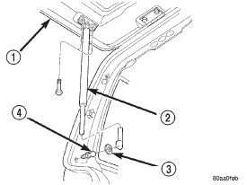
the liftgate (Fig. 89).
(6) Separate the support rod from the liftgate. INSTALLATION (1) Position the support rod on the liftgate.
1 - LIFTGATE (2) Install the bolts attaching the support rod to
the liftgate.
(3) Connect the support rod to the ball stud.
(4) Secure the support rod to the ball stud with
the retainer clip.
(5) Remove the support from the liftgate. REMOVAL (1) Open the liftgate.
(2) Support the liftgate in the open position.
(3) Remove the retainer clip attaching the support
rod to the ball stud.
(4) Disconnect the support rod from the ball stud.
(5) Remove the ball stud. INSTALLATION (1) Install the replacement ball stud.
(2) Connect the support rod to the ball stud.
(3) Secure the support rod to the ball stud with
the clip.
(4) Remove the support from the liftgate. REMOVAL (1) Remove liftgate trim panel.
(2) Disconnect liftgate actuator linkages.
(3) Disconnect liftgate outside handle to latch rod.
(4) Remove nut attaching outside handle to liftgate
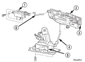
(Fig. 90).
(5) Separate outside handle from liftgate.
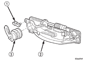
(6) If necessary, remove lock cylinder (Fig. 91).
1 - POWER ACTUATOR
1 - CLIP INSTALLATION (1) If necessary, install lock cylinder.
(2) Position outside handle on liftgate.
(3) Install nut attaching outside handle to liftgate.
(4) Connect liftgate outside handle to latch rod.
(5) Connect liftgate actuator linkages.
(6) Install liftgate trim panel. Liftgate lock cylinder For service procedures, refer to the Liftgate Outside
Handle Removal/Installation procedures.Liftgate support rod cylinder

Fig. 89 Liftgate Support Rod
2 - SUPPORT ROD CYLINDER
3 - WASHER
4 - BALL STUDLiftgate support rod ball stud
Liftgate outside handle

Fig. 90 Liftgate Outside Handle
2 - LIFTGATE LOCK
3 - OUTSIDE HANDLE
4 - OUTSIDE HANDLE TO LATCH ROD
5 - LIFTGATE LATCH
6 - ACTUATOR TO LIFTGATE LOCK ROD
Fig. 91 Liftgate Lock Cylinder
2 - OUTSIDE HANDLE
3 - LOCK CYLINDER
 Liftgate trim panel. Liftgate. Liftgate hinge
 Liftgate latch. Liftgate latch striker. Liftgate weatherstrip
Other materials:
LaneSense Operation. Turning LaneSense ON Or OFF. LaneSense Warning Message
LaneSense Operation
The LaneSense system is operational at speeds above
37 mph (60 km/h) and below 112 mph (180 km/h). The
LaneSense system uses a forward looking camera to
detect lane markings and measure vehicle position
within the lane boundaries.
When both lane markings are detected and t ...
