Jeep Cherokee (XJ): Liftgate trim panel. Liftgate. Liftgate hinge
REMOVAL (1) Using a small flat blade, pry out the trim plugs
from the liftgate assist handle.
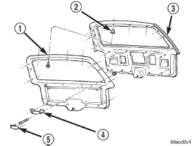
(2) Remove the screws attaching the assist handle
to the liftgate (Fig. 87). (3) Remove the screws that attach the liftgate trim
panel to the liftgate.
(4) Using a trim panel removal tool, detach the
push-in fasteners from the liftgate.
(5) Remove the trim panel from the liftgate.
1 - TRIM PANEL INSTALLATION (1) Position the trim panel on liftgate.
(2) Using new push-in fasteners, align the push-in
fasteners with the holes in the liftgate inner panel
and press the trim panel into place.
(3) Install the screws to attach the liftgate trim
panel to the liftgate.
(4) Install the screws attaching the assist handle
to the liftgate.
(5) Press the trim plugs into the liftgate assist
handle. REMOVAL WARNING: DO NOT DISCONNECT SUPPORT ROD
CYLINDERS WITH LIFTGATE CLOSED. SUPPORT
ROD PISTONS ARE OPERATED BY HIGH PRESSURE
GAS. THIS COULD CAUSE DAMAGE AND/OR
PERSONAL INJURY IF THEY ARE REMOVED WHILE
PISTONS ARE COMPRESSED.
(1) Remove center high mounted stop lamp
(CHMSL).
(2) Open and support liftgate.
(3) Remove liftgate trim panel.
(4) Disconnect and plug backlite washer fluid supply
line.
(5) Remove screws that attach rear wiper and liftgate
power lock wire harness connectors to liftgate
and disconnect connectors.
(6) Using access hole created by removal of
CHMSL, route backlite washer fluid supply line and
rear wiper and liftgate power lock wire harness/
grommets through access hole and separate from liftgate.
(7) Remove retainer clips that secure support rods
to ball studs.
(8) Remove support rods from ball studs.
(9) Remove bolts attaching hinges to liftgate.
(10) Remove liftgate from vehicle. INSTALLATION (1) Position and support liftgate at opening in body
and install bolts attaching hinges to liftgate. Tighten
bolts to 26 N·m (19 ft. lbs.) torque.
(2) Connect liftgate support rods to ball studs and
install retainer clips.
(3) Route backlite washer fluid supply line and
rear wiper and liftgate power lock wire harnesses/
grommets through access hole.
(4) Connect connectors and install screws that
attach rear wiper and liftgate power lock wire harness
connectors to liftgate
(5) Unplug and connect backlite washer fluid supply
line.
(6) Install liftgate trim panel.
(7) Remove supports and close liftgate.
(8) Install (CHMSL). REMOVAL It is not necessary to remove the liftgate to replace
one or both hinges.
(1) Open and support the liftgate.
(2) Remove the liftgate opening upper trim.
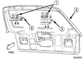
(3) Remove the bolts attaching the hinge to the
header panel (Fig. 88).
(4) Remove the bolts attaching the hinge to the
liftgate.
1 - LIFTGATE HINGE INSTALLATION (1) Position the hinge on the liftgate.
(2) Install the bolts attaching the hinge to the liftgate.
Tighten to 26 N·m (19 ft. lbs.) torque.
(3) Install the bolts attaching the hinge to the
header panel. Tighten to 26 N·m (19 ft. lbs.) torque.
(4) Install the liftgate opening upper trim.
(5) Remove the support and close the liftgate.Liftgate trim panel

Fig. 87 Liftgate Trim Panel
2 - PUSH NUT
3 - LIFTGATE
4 - ASSIST HANDLE
5 - PLUGLiftgate
Liftgate hinge

Fig. 88 Liftgate Hinge
2 - LIFTGATE
3 - HEADER PANEL
4 - HEADER PANEL
 Rearview mirror support bracket. Sunvisors. Headliner
 Liftgate support rod cylinder. Liftgate support rod ball stud. Liftgate outside handle
Other materials:
Instrument panel assembly
WARNING: ON VEHICLES EQUIPPED WITH AIRBAGS,
REFER TO GROUP 8M - PASSIVE
RESTRAINT SYSTEMS BEFORE ATTEMPTING ANY
STEERING WHEEL, STEERING COLUMN, OR
INSTRUMENT PANEL COMPONENT DIAGNOSIS OR
SERVICE. FAILURE TO TAKE THE PROPER PRECAUTIONS
COULD RESULT IN ACCIDENTAL AIRBAG
DEPLOYMENT AND POSSIBLE ...
